Final Design
After months of learning and experimenting with circuitry, software, 3D design, and printing, I’ve completed the final layout and design of my Kerbal Space Program controller.
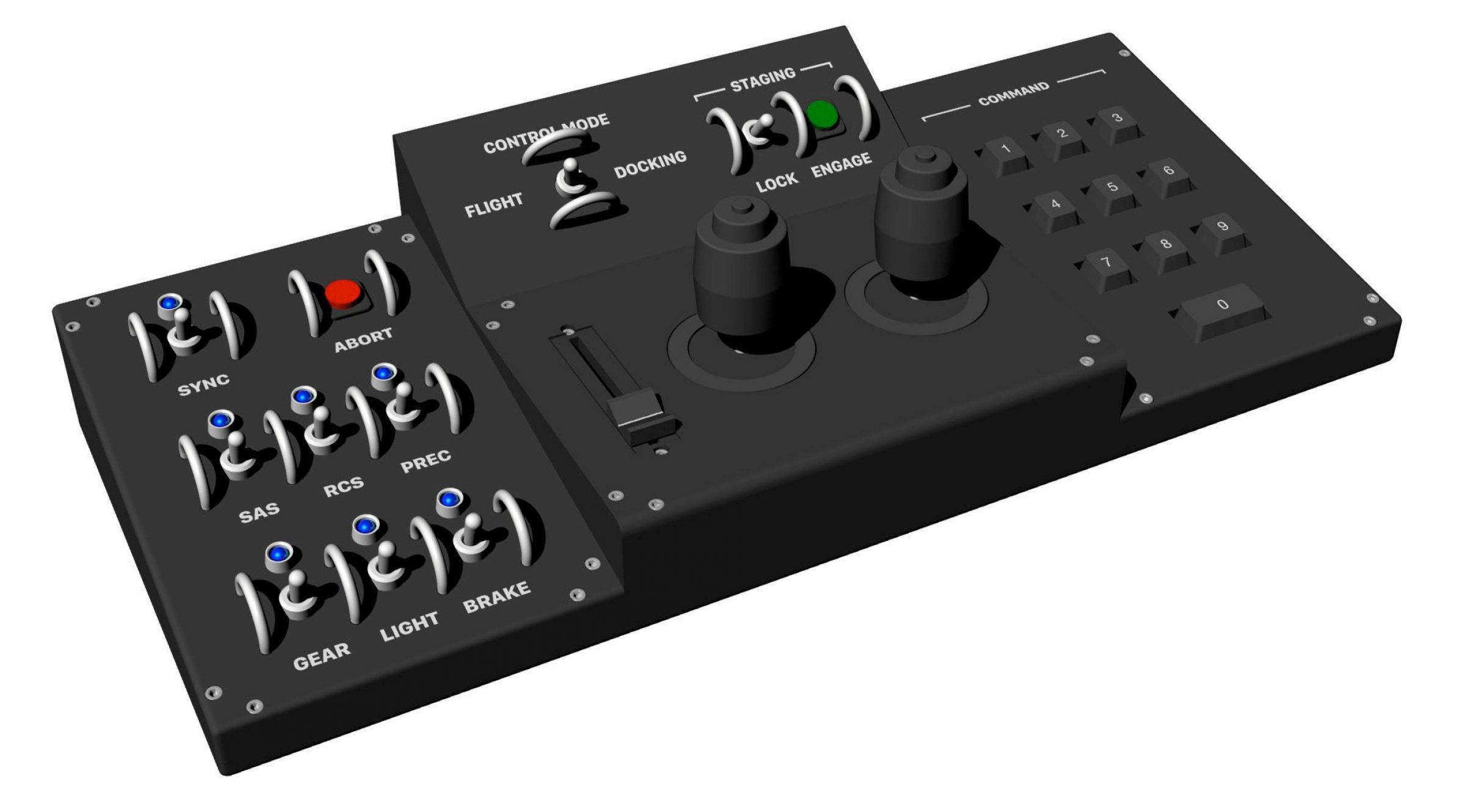
The fully-assembled controller is 19 inches wide, 8.3 inches deep, and 4.5 inches high. The center panel is home to the throttle slider and two joysticks used for spacecraft control—pitch, roll, and yaw for attitude, and forward/back, left/right, up/down for translation (for docking).
Above them are controls for control mode toggle (flight and docking modes), and staging. The toggle switch will lock staging to prevent accidental RUDs—rapid unplanned disassemblies—and the green button will trigger stage separation.
The panel to the left contains all sorts of controls—abort, landing gear, lights, brakes, and so on. On the right are the 0-9 buttons for configurable controls.
On the back of the controller is a USB port to connect to the computer. In addition to carrying control signals, the USB cable provides power for the LEDs on the controller.
Slicing the Structure
My printer can print a maximum size of just under 9 x 6 x 6 inches. That means for a piece this big, I have to break it up into sizes I can fit on the print bed. Here’s an exploded view of the printed pieces, so you can get a sense for how it’s broken up:
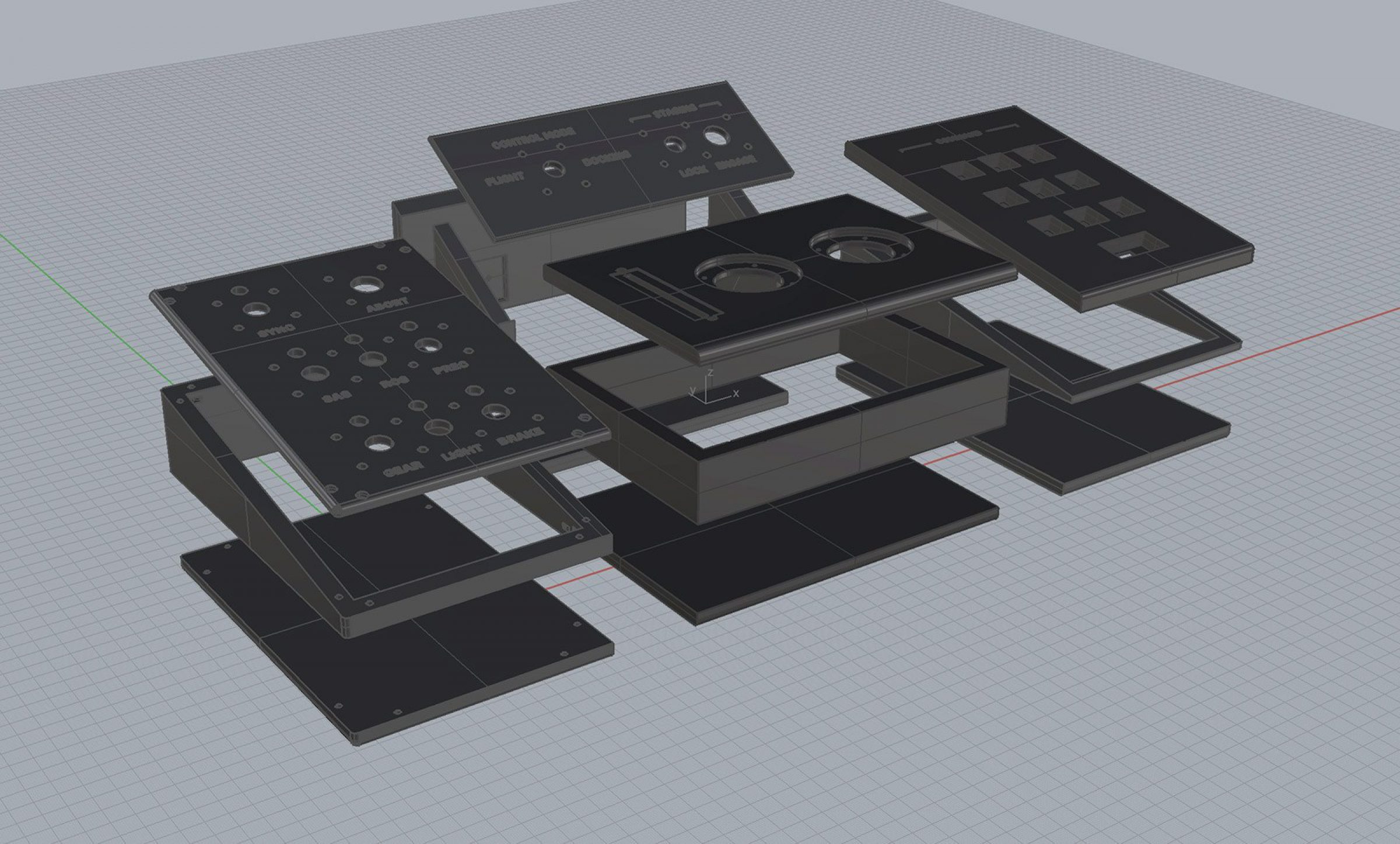
In general, the base, walls, and top are distinct pieces with holes cut out for nuts and bolts to bring everything together. Due to their sheer size, some of these pieces are going to take the better part of a day to print.
Chips and Circuitry
As I showed in previous posts, a Teensy++ 2.0 will be the brains of the controller. That chip will live just inside the back panel of the controller, mounted on a breadboard which will be bolted to the bottom of the case.
Every component will ultimately connect to the main board, but there will be smaller breadboards at other locations inside the case to keep each location simpler and less cluttered. The inner walls of the controller contain cut outs for routing wires and harnesses for securing them.
The Home Stretch
The design is finalized, the circuits are drawn up, and the software has been tested. From here, I’m heading into final printing, assembly, and installation. I’m on the home stretch now—my next post will be filled with photos of the first pieces coming off the printer.