Component Tests
It’s been a while since my last post about my Big Cartel Employee Art Grant project. I’ve been busy sourcing components, working on various mounts and enclosures, fixing a handful of broken and jammed extruders on my 3D printer, and designing the final product.
Sourcing and Testing Components
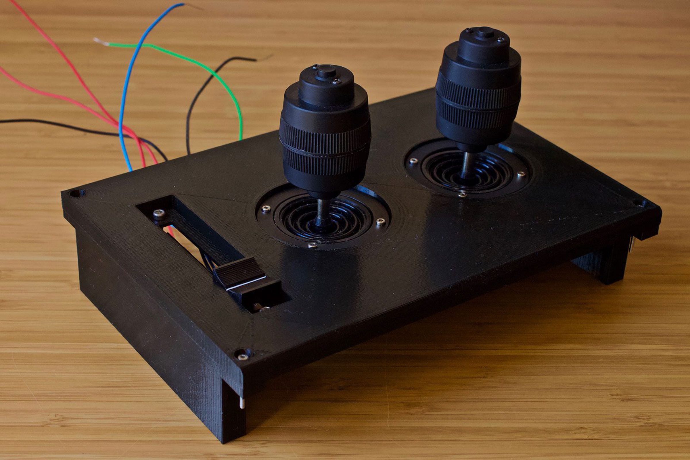
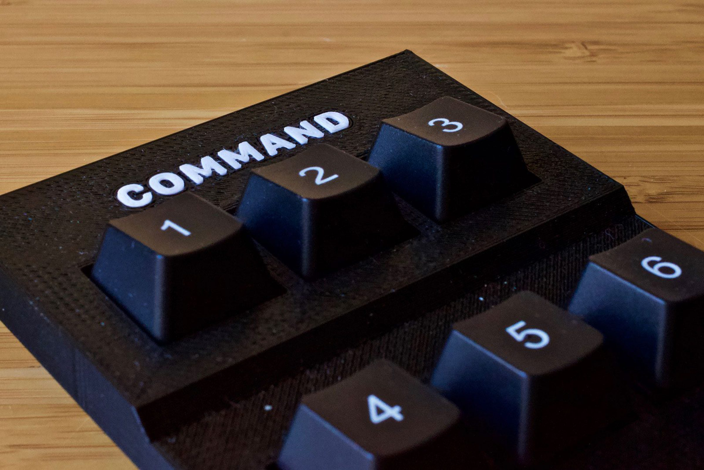
The final few components I needed to get my hands on were some of the more important ones: 3-axis joysticks (plus one button) for spacecraft attitude control, a large slide potentiometer (and a comfy knob) for the throttle, and Cherry MX keys (black, plate-mounted keyswitches with white-on-black numeric keycaps) for 0-9 command buttons.
With new parts in hand, I started individual component tests. Each test consisted of a small print to verify how each component would be mounted into the final product, and to figure out exactly what kind of tolerances were needed to make sure everything fit together perfectly. I worked my way up from small tests to larger ones—combining two or three components together in the way they’d coexist in the final product.
With some of these prints, I began testing how I’d handle the text inlays needed for labeling the controls. The main body of the control panel is printed in black, with space left in the surface for the text inlays. The letters are printed separately in white, and then are inserted into their position with a touch of glue.
At this point, I’ve nailed down the specifications for mounting every component—joysticks, throttles, Cherry MX keys, basic push buttons (with an integrated LED), toggle switches, toggle switch guards, small LEDs, and the USB port used to connect the panel to a device. You’ll see all of those components in the design for the final product in my next update.
It’s What’s on the Inside
The 3D-printed enclosures are only half of this project—the other half is all about the circuitry and software that make up the brains of the controller. In my first post about this project, I showed off the original prototype, which was run on an Arduino Leonardo. The Leonardo is a pretty useful Arduino board which can emulate USB mice and keyboards. What that means is that it can take input from a physical button or switch and report that as a keypress or mouse event to the attached device—think of it like a translator from physical events to actions on your computer.
That worked pretty well, but I found something even better: the Teensy++ 2.0.
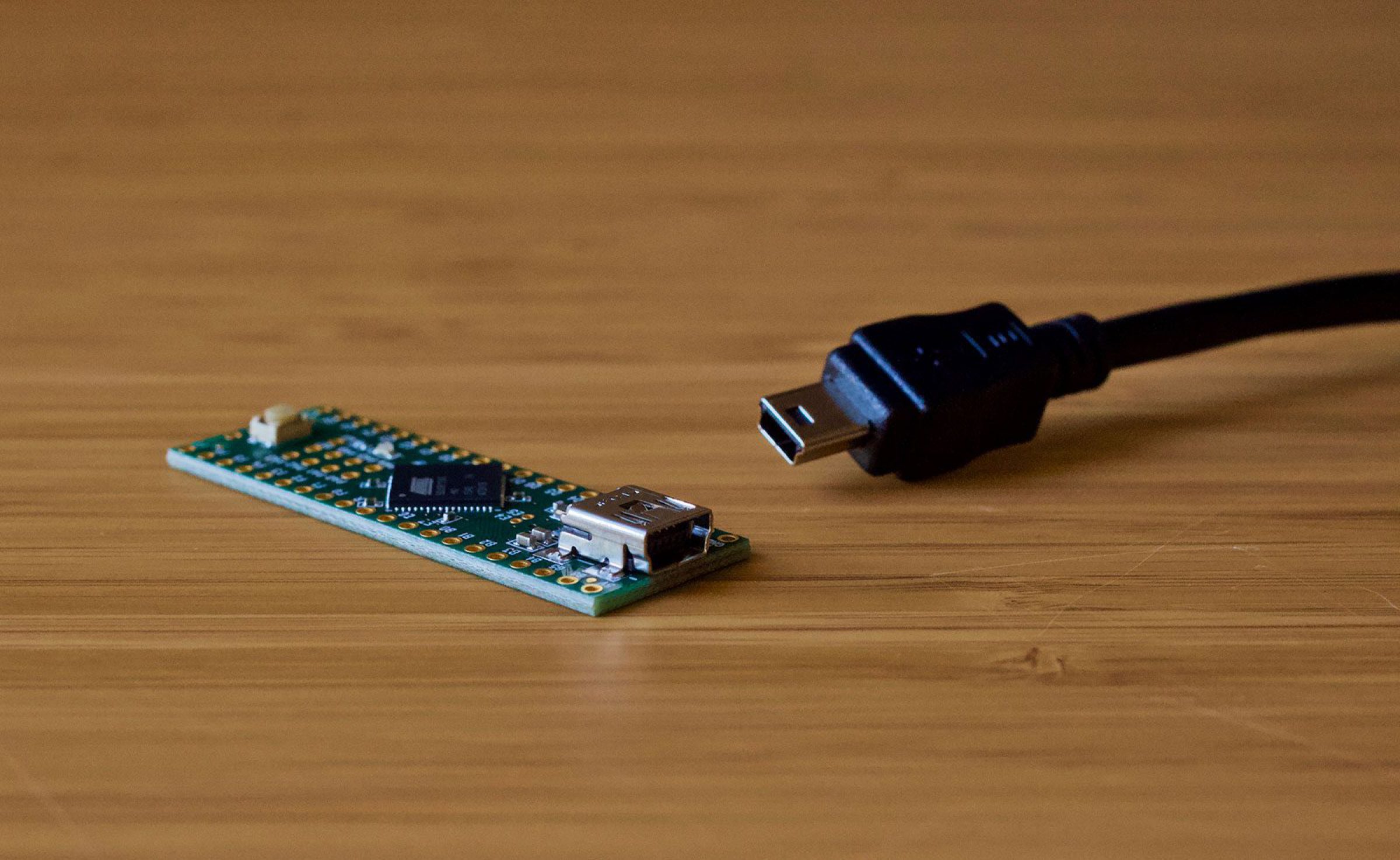
And they’re not lying when they say Teensy. That’s a standard USB Mini-B port like you’d find on cameras or other handheld-size devices. Other than its small size, there are two main advantages of the Teensy++ 2.0 over the Arduino Leonardo.
First, it has an incredible amount of input pins (all those gold circles you see lining the edge of the board), which means it’s easier to connect a large amount of buttons, switches, and other components. That’s a huge help to this project, because I’ll be connecting 2 joysticks (with 3 axes and 1 button), 1 throttle, 10 keyboard-type buttons, 10 toggle switches, and 2 push buttons with LEDs. The more inputs the better.
The second, and more important, advantage is that the Teensy++ 2.0 can emulate USB joysticks and gamepads, not just mice and keyboards like the Leonardo. That means it can take input from an analog axis, like a joystick, and report that to the attached device as a control axis directly, rather than mimicking axis-type control with a series of keypresses. This ability gives the controller incredibly smoother control with much more precision.
Better yet, the Teensy++ 2.0 USB joystick-and-gamepad ability cuts down the amount of code I’ll need to write myself by a huge margin. Instead of reading individual component signals and handling that logic, I can assign input pins act as joystick buttons or axes, and Teensy knows exactly what to do with those.
All I need to do to assign specific pins to joystick axes is:
Joystick.X(analogRead(0));
Joystick.Y(analogRead(1));
Joystick.Z(analogRead(2));
This small snippet of code assigns analog pin 0 to the X axis, 1 to the Y axis, and 2 to the Z axis. The code for buttons is just as easy:
Joystick.button(1, digitalRead(0));
Joystick.button(2, digitalRead(1));
This snippet is all that’s needed to assign digital pin 0 to joystick button number 1, and digital pin 1 to joystick button number 2.
Once that code is written and uploaded to the Teensy board, all that’s left is to connect the components to the appropriate pins, and the controller is up and running.